|
Introduction
|
!!!!- DISCLAIMER -!!!!
I take no responsiblity for any damages that may occur when working on your car.
YOU WILL BE WORKING WITH A/C POWER! IT HURTS! BE VERY CAREFUL!
This equipment is EXTREMELY FRAGILE and cannot be bought in seperate pieces.
If you want to replace a piece, take your ass to the junkyard, or be prepared to buy the whole cluster from Toyota for $900!
|
|
| |
|
Materials Needed
|
16x6 piece of Electroluminescent sheet
Power inverter for EL sheet
Cutting instruments (Xacto knife)
Screwdrivers
2 spoons or a pry tool to take off the needles
InkJet or whatever printer you have Transparencies (office supply stores)
Laminate (don't heat)(enough to cover both sides of the material)
White stencil film (for the color of the gauges -daytime)
Scanner
A Girlfriend to yell at you when you spend too much time on this
Printer
Clear Packing tape
Stuff to wire up inverters to your car
|
|
| |
|
Step 1 - Take your gauges out.
|
I found out how to do this HERE.
Instructions thanks to ByeByeBaby who wrote the howto and posted it on NewCelica.Org
|
|
| |
|
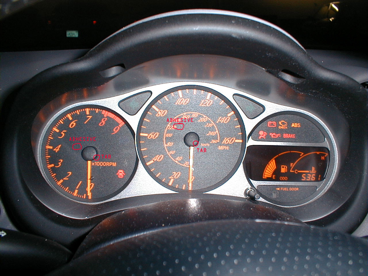
Step 2 - Pull off your gauge face.
|
There are 2 little tabs by the openings for the needles, and some adhesive opposite of the needles fairly near the hole. If it appears to be sticking too much, hold it by a light bulb for a minute or so to loosen up the adhesive.
|
|
| |
|
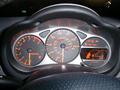
Step 3 - Scan your gauges
|
I'd post my scan, but the file is extremely enormous....
Remember, the better quality the picture, the easier it will be to select stuff in photoshop or whatever program you will use.
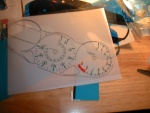
You will need to make:
- An image for the actual gauge face which consists of:
(Print on Transparency)
- a transparent background
- outlines for the whole thing
- outlines for all of the holes. This includes holes for needles, gas/temp gauge and alignment pins.
- all of the ticks, numbers and writing
- your girlfriend not hate you every night that you work on this.
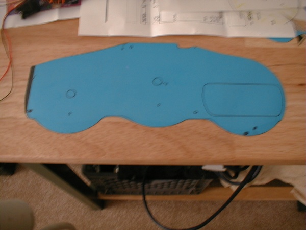
Templates for cutting the Electroluminescent Sheet (you can make this on a transparency). This will include holes for:
- Indicators
- Turn signals
- Needles
- Alignment pins
MAKE SURE THAT MEASUREMENTS ARE EXACT AND YOU CAN PRINT IT TO THE EXACT SIZE OF THE GAUGE FACE
(You may need to find paper and transparencies larger than standard 8 1/2" X 11" Letter)
(You may also rotate the image so that it fits (for the most part) on letter)
|
|
| |
|
|
| |
|
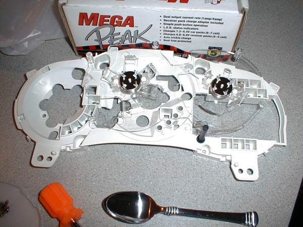
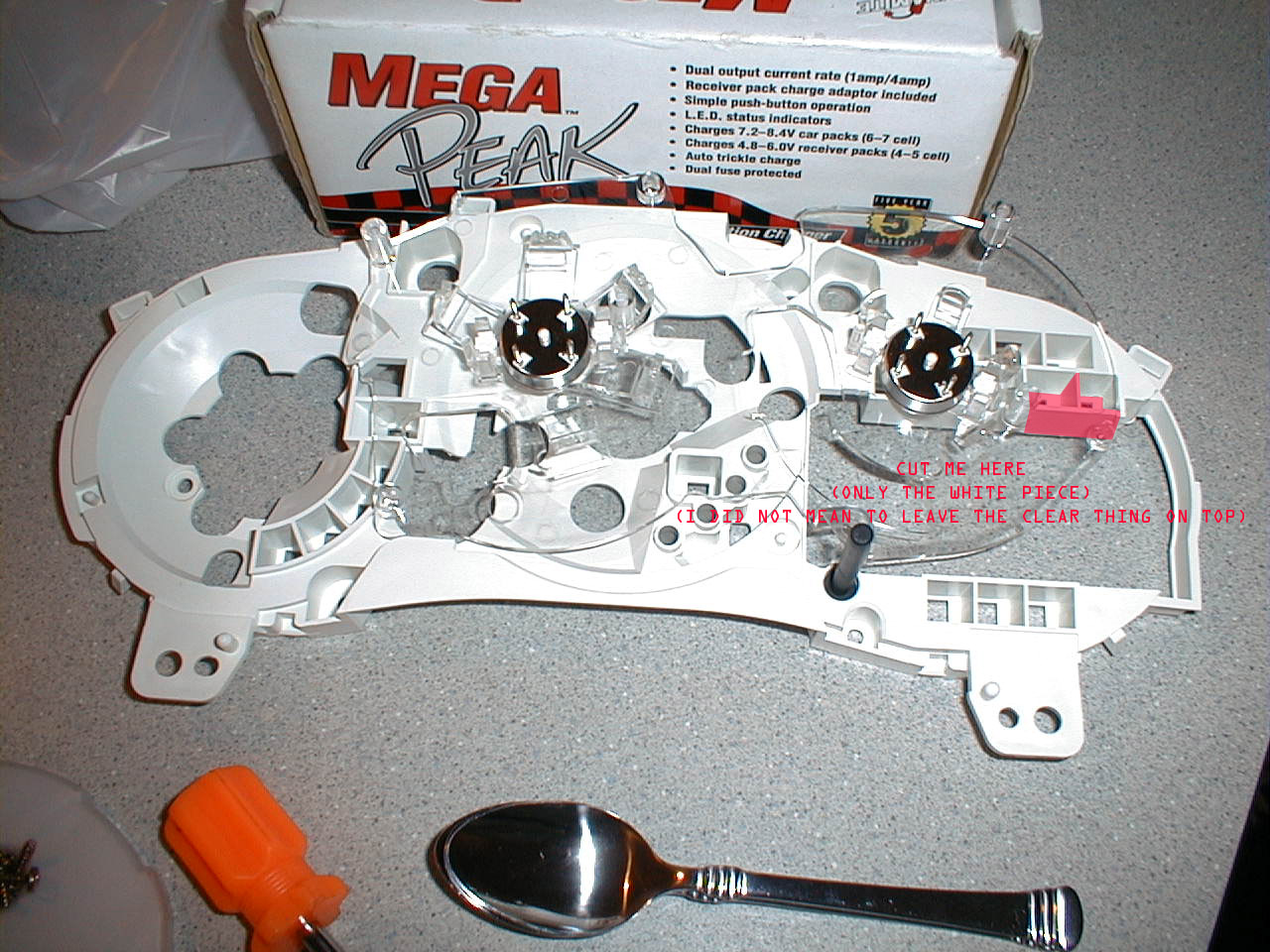
Step 5 - Finish taking your gauges apart.
|
Make sure you've taken off all of the screws on the back of the gauge cluster
Wiggle the clear plastic piece w/the pins off of the holes that the pins go into the circuitboard in.
Remove the White Piece under the clear piece you just took off
You will now be left with the circuitboard


|
|
| |
|
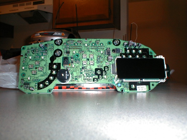
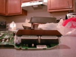
Step 6 - Removing the LCD
|
Ok... I have to stress yet again .. BE CAREFUL!!!!! and I AM NOT RESPONSIBLE IF YOU BREAK YOUR CAR!
These pieces are quite fragile and it almost sounds/feels like you break them when you remove them...
You have been warned.. Proceed with caution if you wish.
The LCD is held in only by 4 clips that clip to the back of the circuitboard, and the pins on the bottom of the screen into the connector on the circuitboard.
Undo the clips, and gently push on the white nubs that stick through the circuitboard. Gently rock the puppy out.. It takes time, patience, and a steady hand... DO NOT RUSH YOURSELF I didn't break mine, so why should you?
|
|
| |
|
|
| |
|
Step 8 - Finish up the EL
|
Attach connections to EL (check beingseen.com's site)
LAMINATE THE EL, IF YOU DON'T, HUMIDITY CAN GET INSIDE AND THAT'S BAD M'KAY?
This step is pretty much explained w/the pieces of EL you got
|
|
| |
|
Step 9 - Assemble
|
You will now have to put everything together and wire it in.
In terms of wiring, follow beingseen's instructions for hooking up the inverters to the EL, and to 12V power (parking light wire or other)
Place the EL on top of the stock gauges, making sure you have enough clearance between it and the needles. They can get stuck. Trust me on this one.
Once you've put everything back together, take it down to the car and try it out!
|
|
| |
|
Outro
|
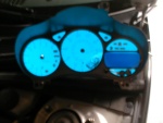
Pictures taken during creation & planning
|
|
| |